Problem
To manufacture a working engine powered by compressed air using BS8888 Engineering Drawings within 4 weeks
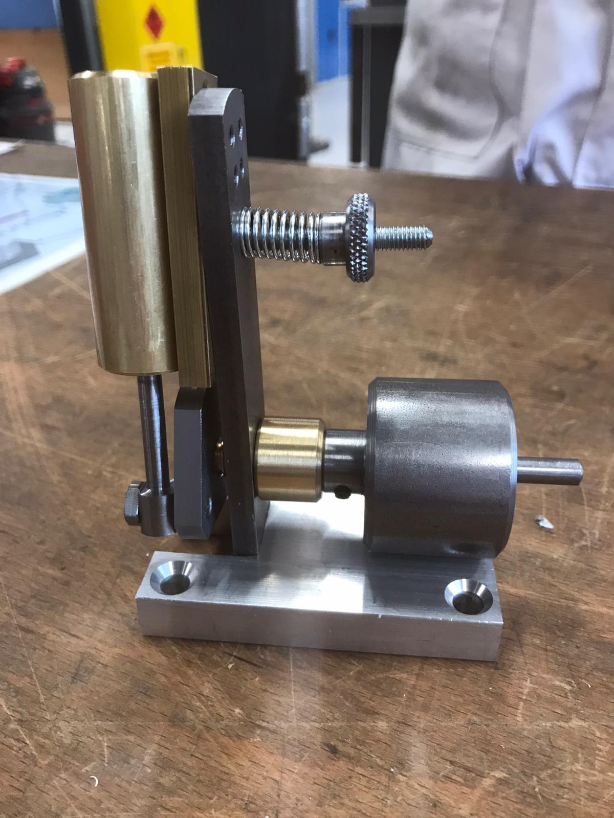
Solution
The final Air Engine
Manufacturing Plan
The first week of the project was dedicated to splitting up the 15 parts between our group of 6. We did this by splitting into three groups of 2, of who worked efficiently and effectively with each other, and assigning 5 parts to each group with varying difficulty.
We then had to produce a detailed manufacturing plan for each of the parts before we were able to manufacture, an example of the manufacturing plan for the upright is shown in the image.
The last three weeks of the project were allocated to manufacturing in the workshop, running alongside our university lectures. Therefore, time management and keeping the group organised is fundamental in completing the project.
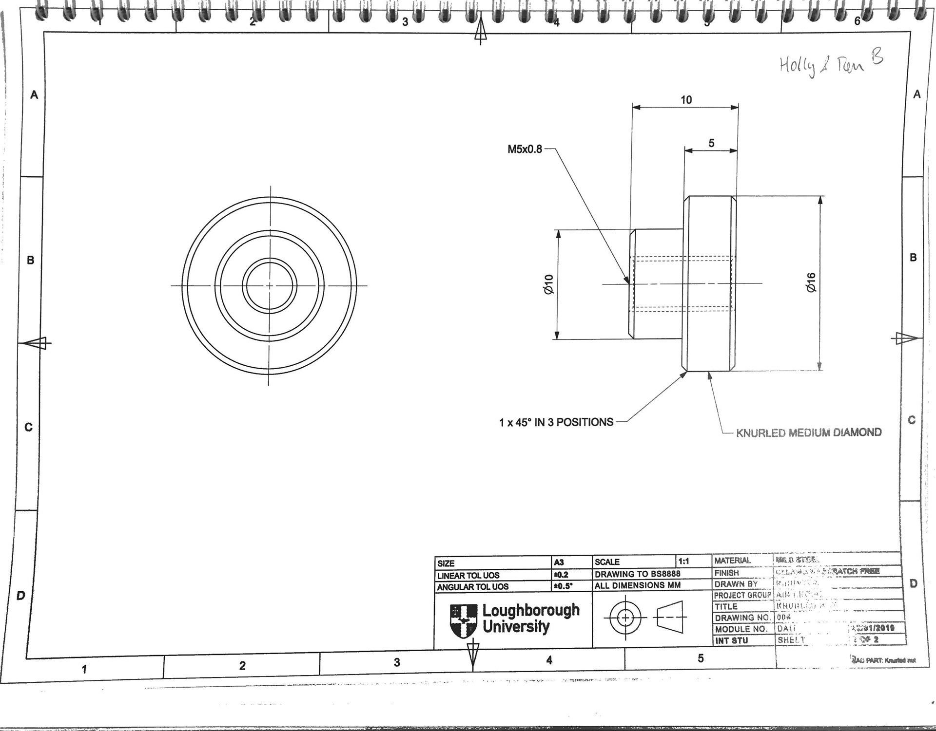
Engineering Drawings
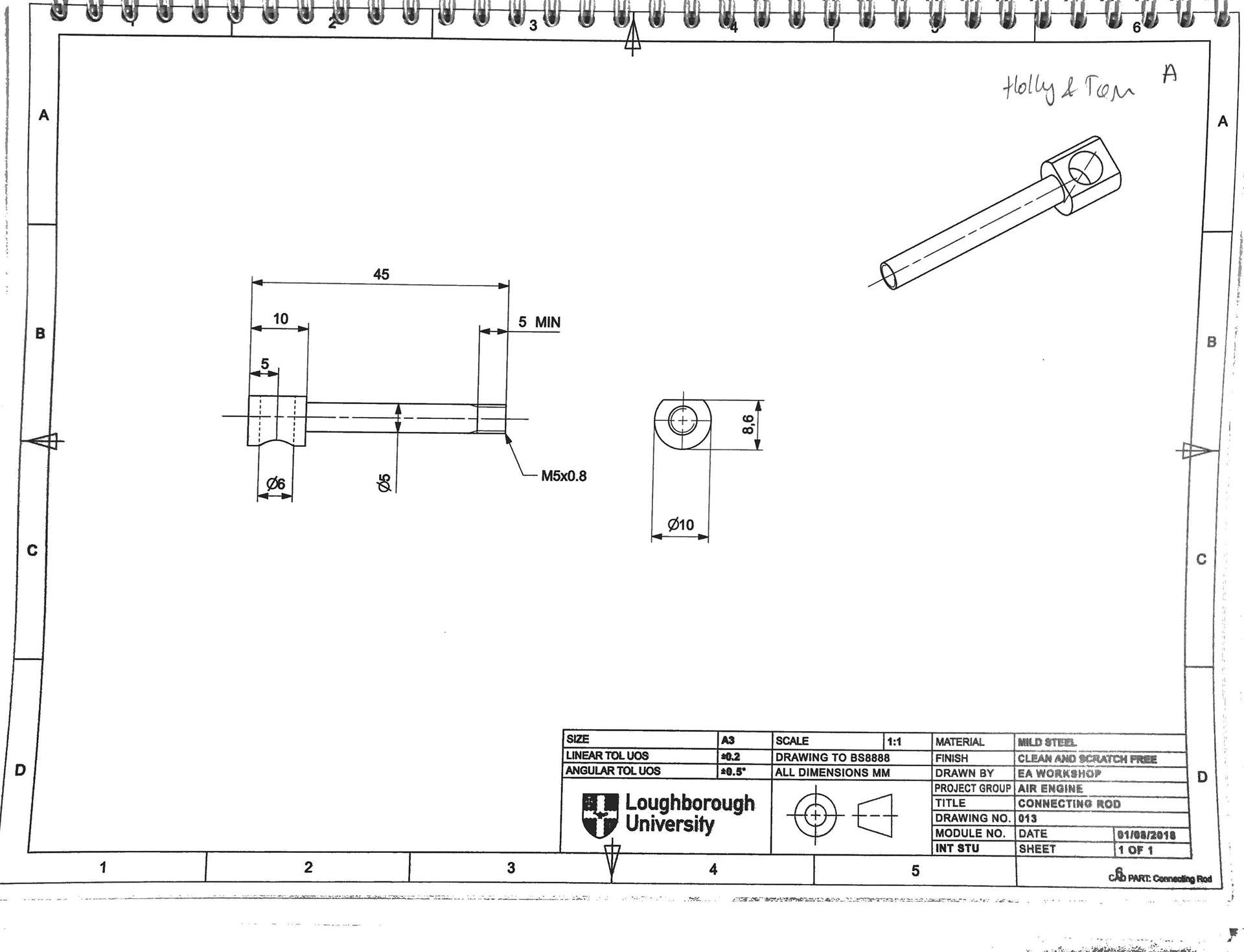
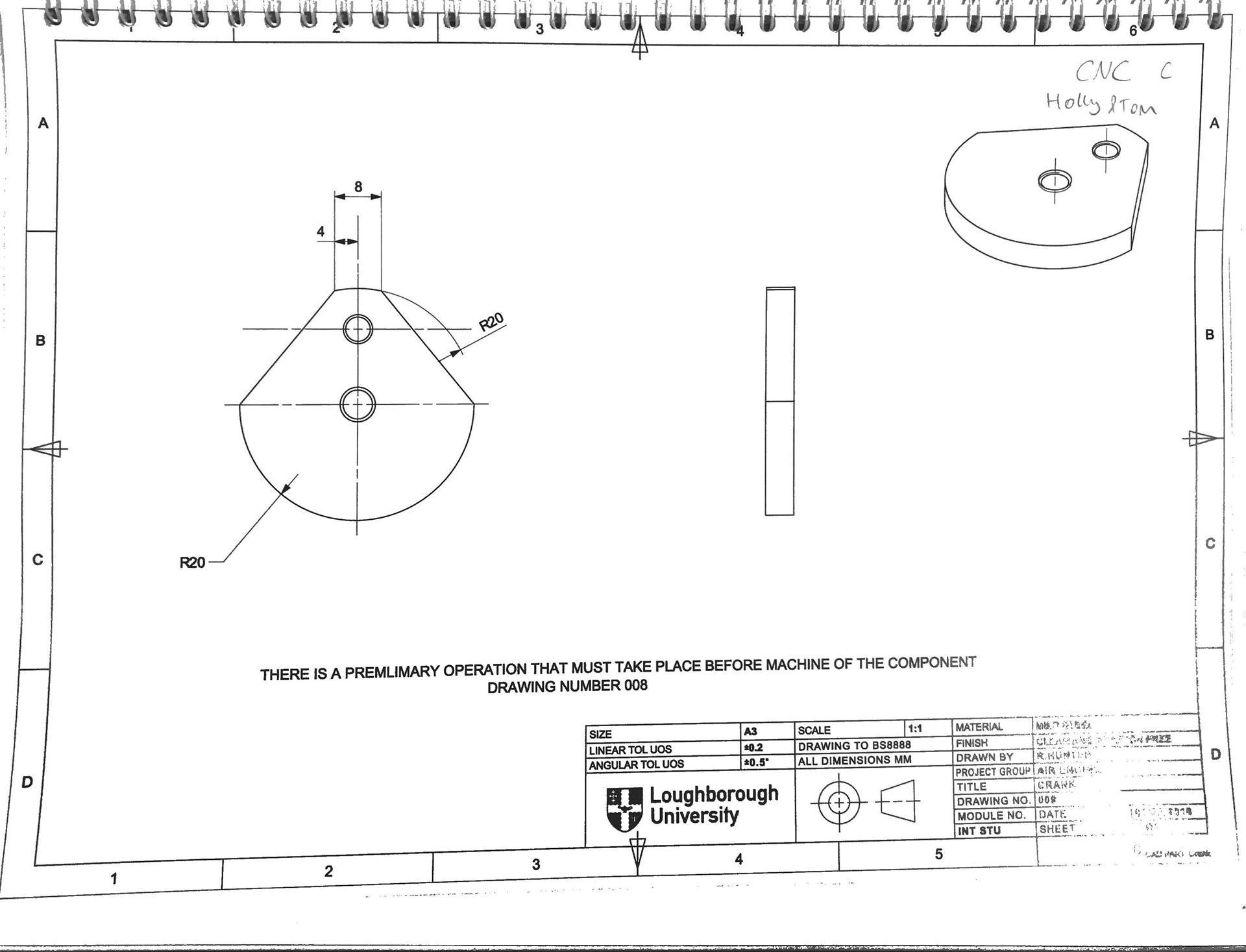
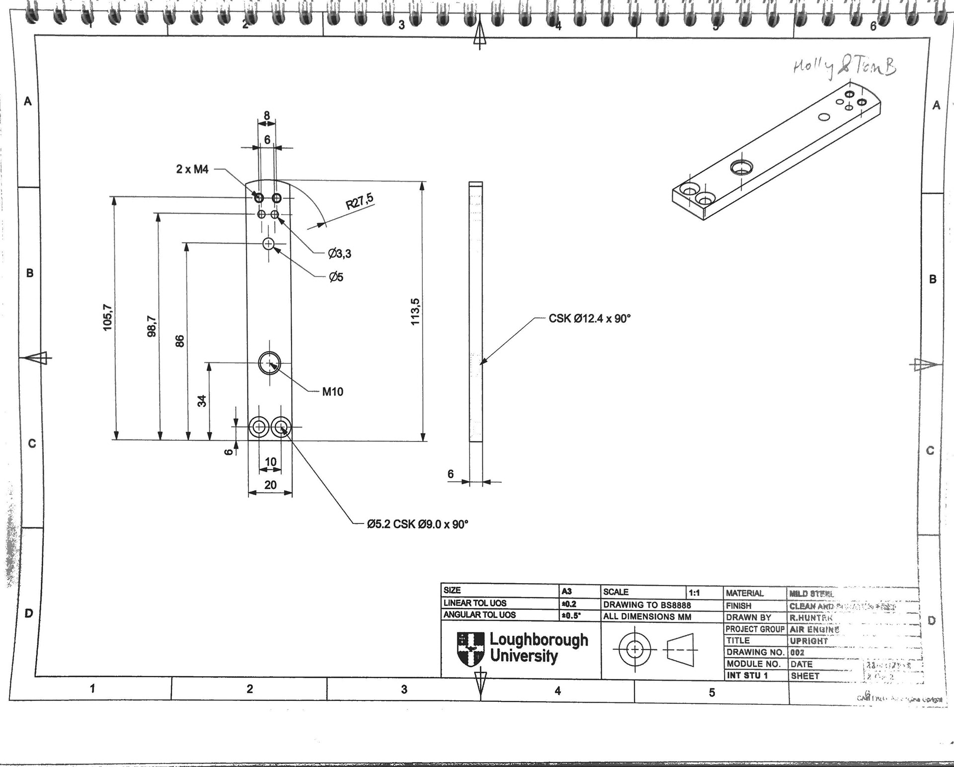
The four BS888 Engineering Drawings below where the parts that I was responsible for manufacturing. These drawings clearly show the manufacturing tolerance for the parts, which is crucial to be within otherwise the part would be rejected.
CNC Manufacturing
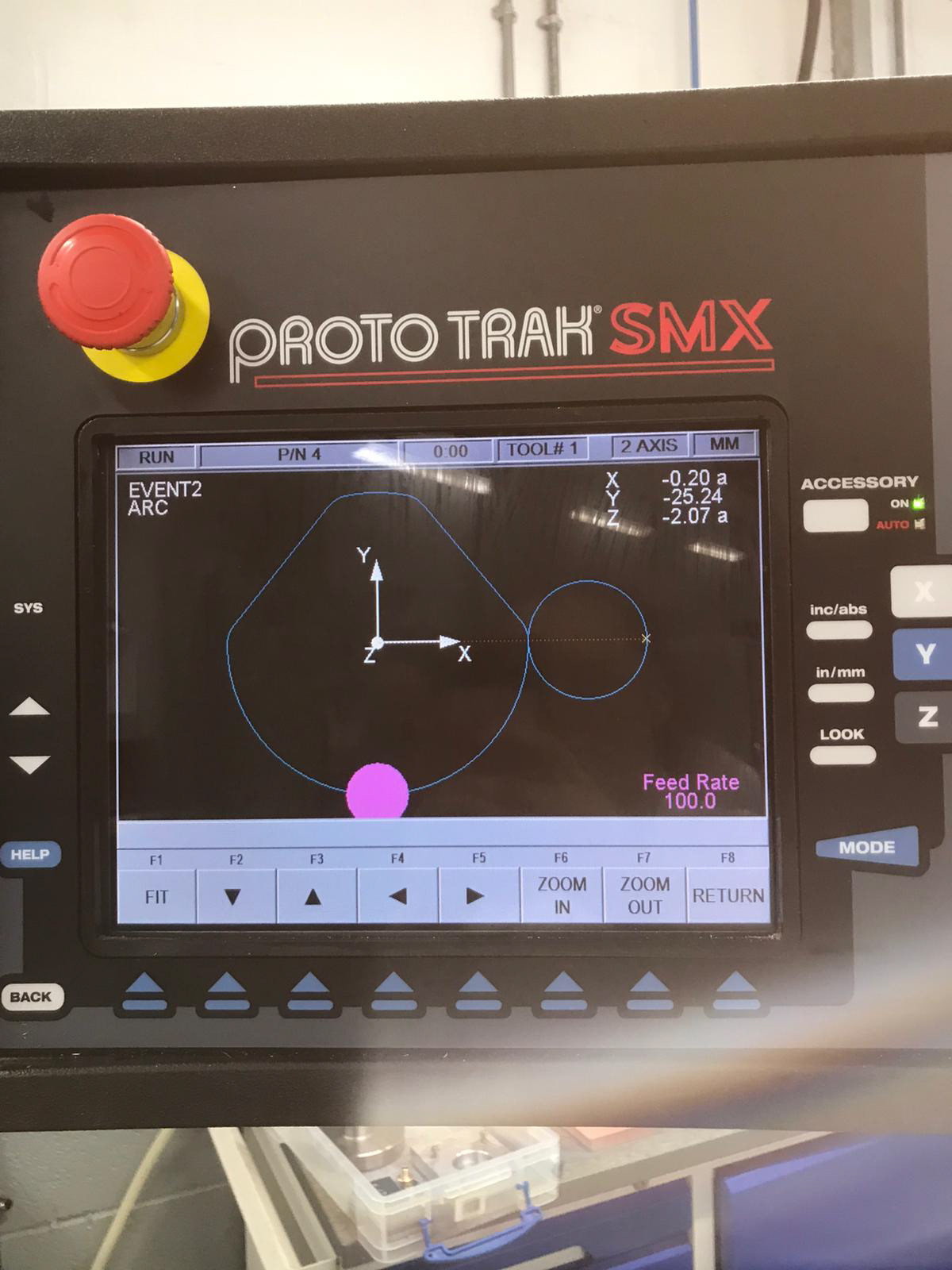
Due to the complexity of the part, the crank was manufactured on the CNC Milling machine. This part required further calculations to the engineering drawing provided such as the spindle speed of the cutting part. Geometry was also used to calculate the coordinates to input into the CNC Milling machine to cut the outline of the shape.
The cutting outline is shown in the image on the right. It was important to take the diameter of the cutting tool into consideration.
Manual Manufacturing
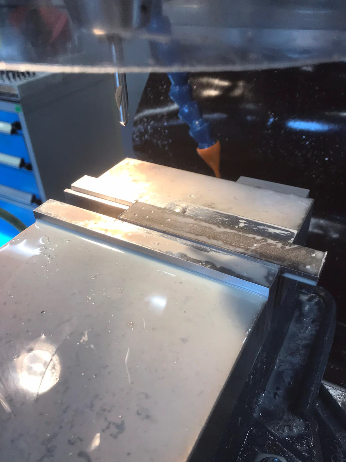
Raw materials were provided in block form and manufactured from scratch. They were scrapped if they were not within tolerance so great care was taken in the fabrication of the parts.
Using the datum function and using the electronic interface as a guide on the milling machine to accurately remove material. To check we were in tolerance, micrometers and vernier calipers were used.
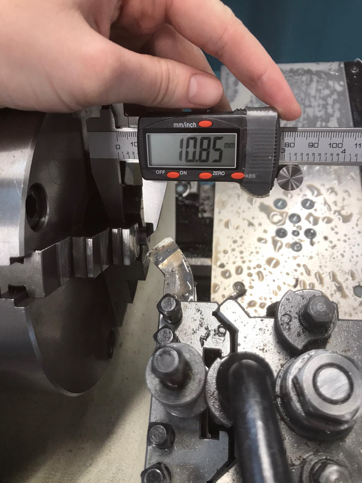
KNURLED NUT - Using a Vernier caliper to ensure the part in within tolerance
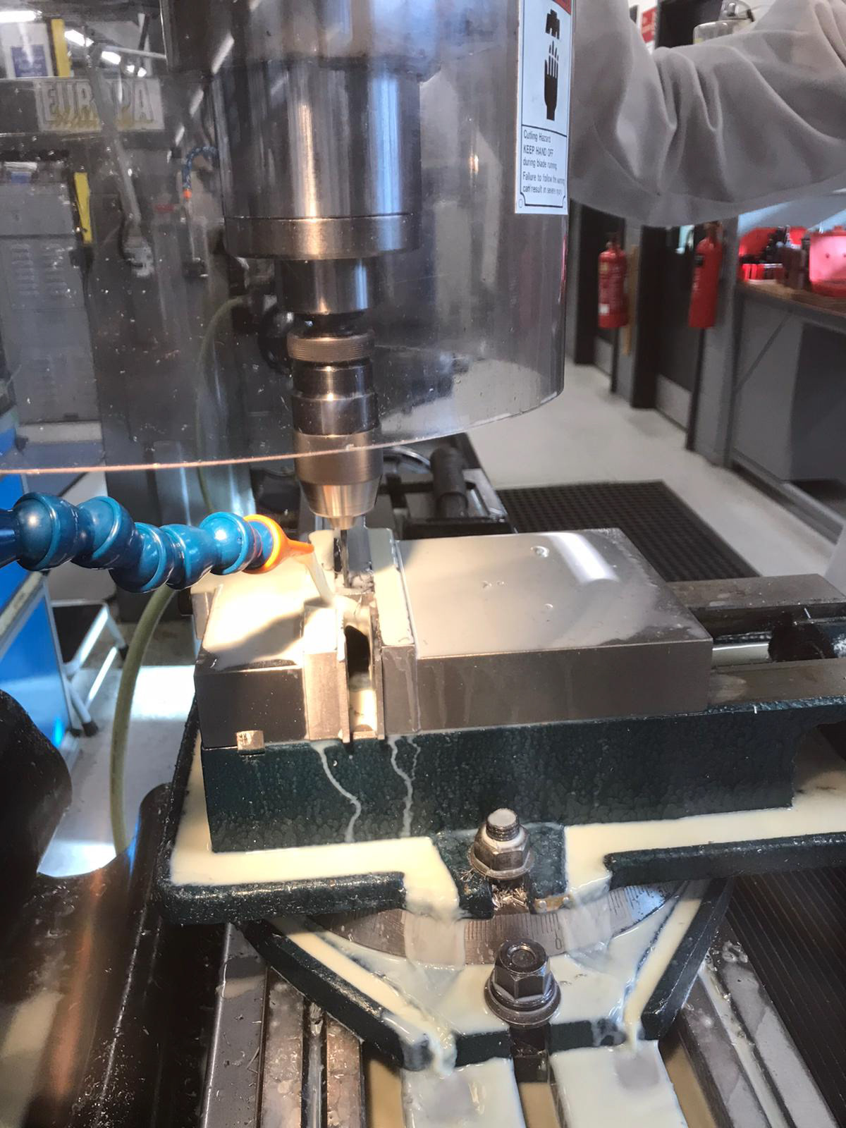
UPRIGHT - Drilling the holes on the milling machine
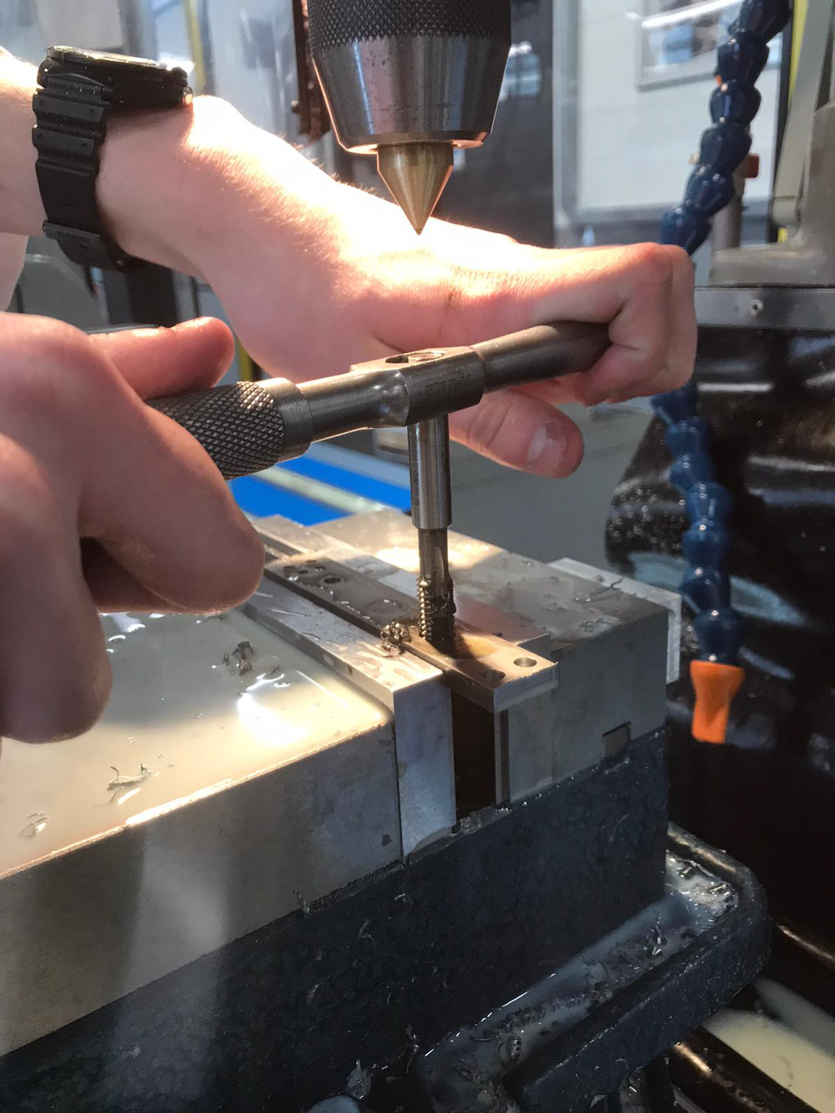
UPRIGHT - Tapping the holes on the milling machine
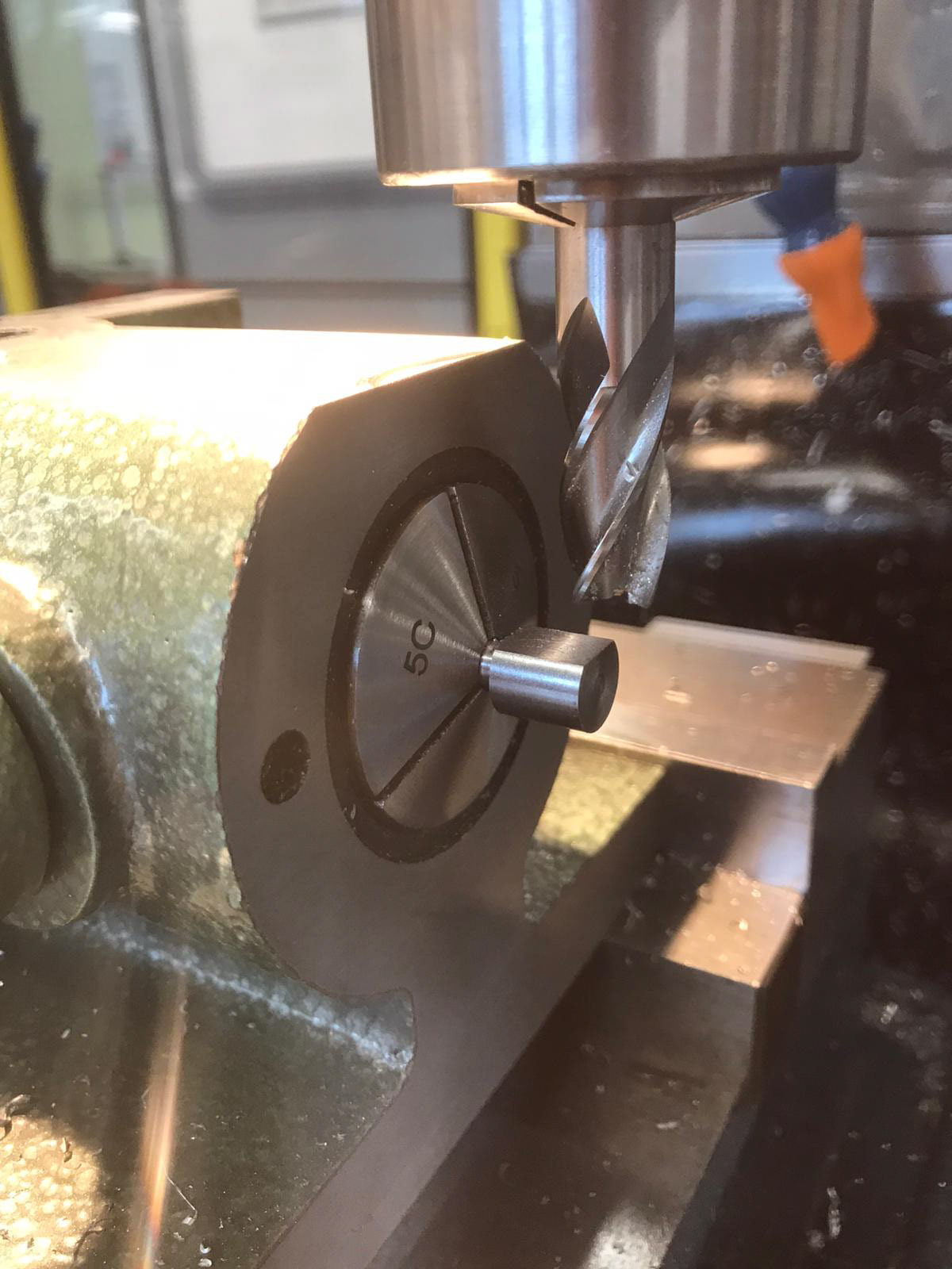
CONNECTING ROD - Facing off the connecting rod
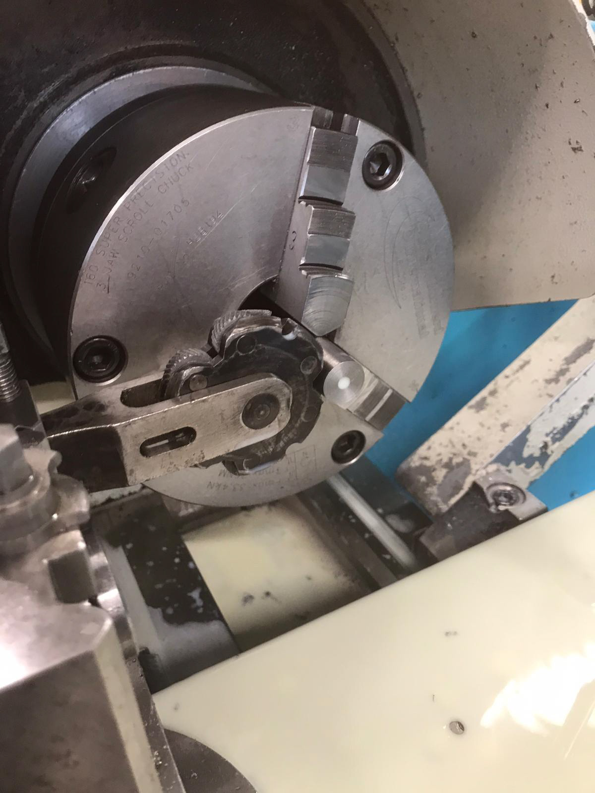
KNURLED NUT - Knurling the nut on the lathe
UPRIGHT - Spotting and drilling the holes on the milling machine
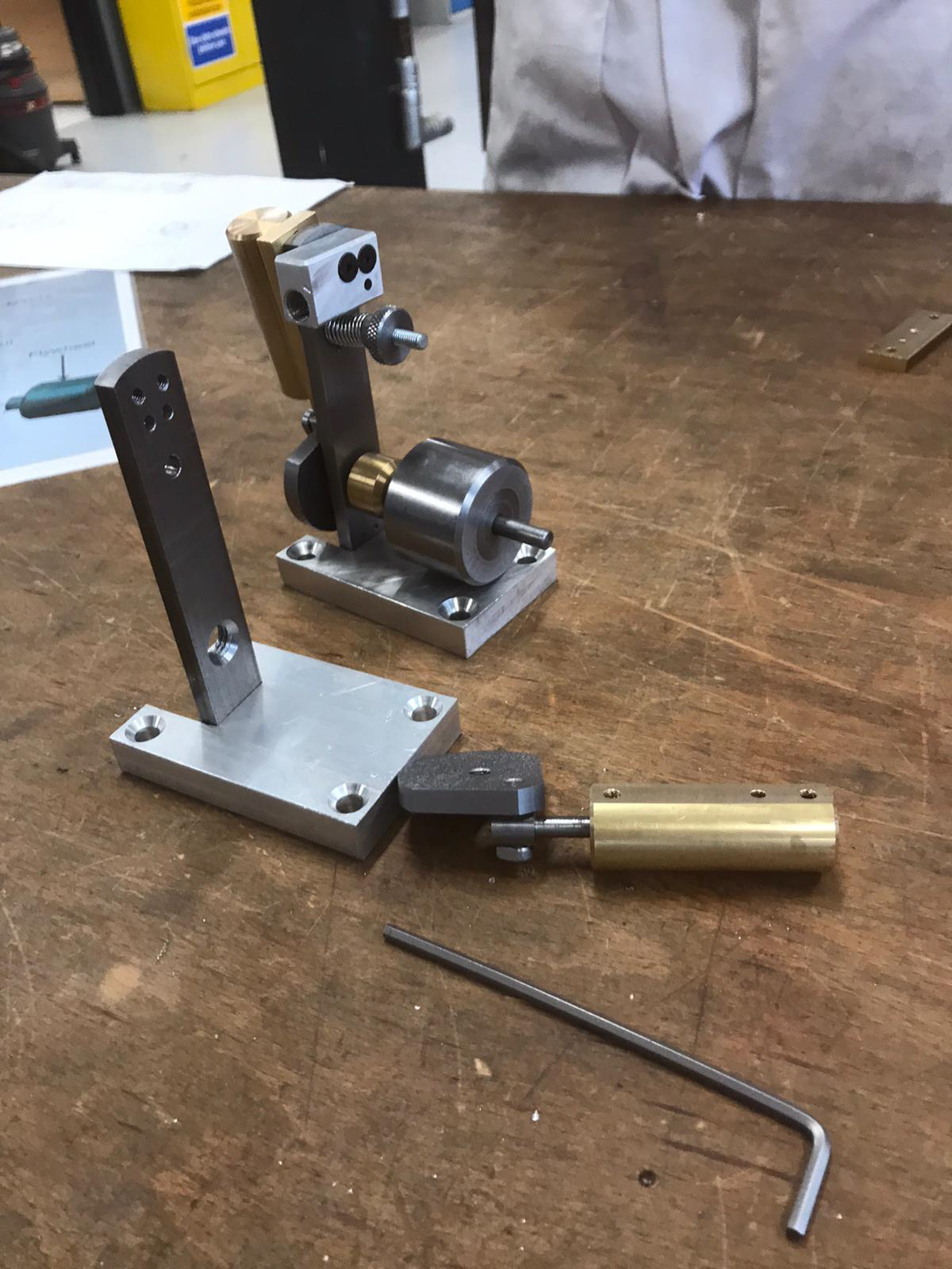
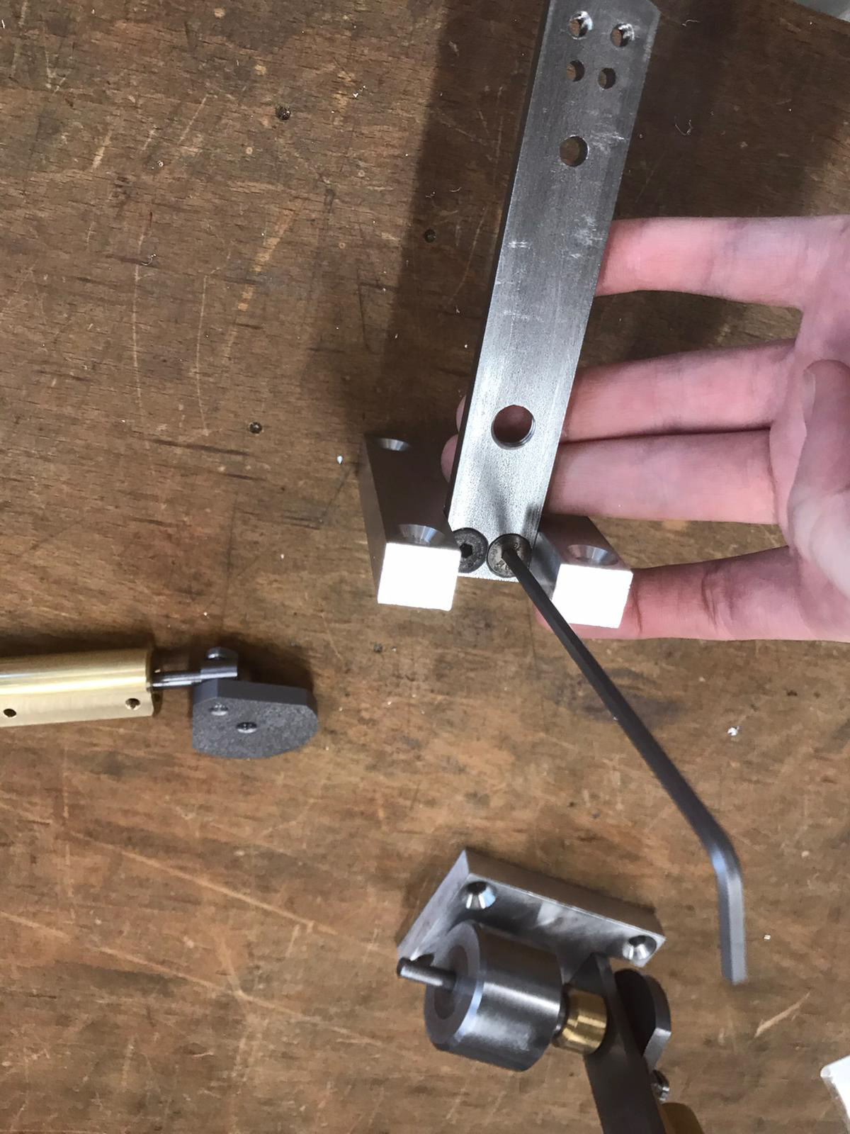
ASSEMBLY
During the assembly stage, a pre-existing air engine and an exploded drawing was used as a guide to ensure our air engine was assembled correctly.
All of our pieces were within tolerance and fit together perfectly.